P-Series P6
2Track Bar Tension
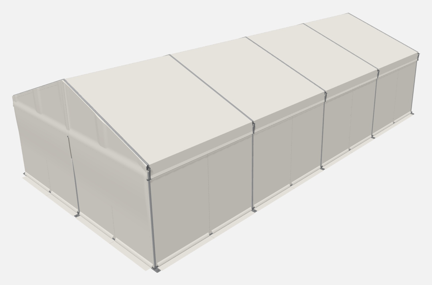
6m span, bar-tensioned roof, any length in 3m bays. 15 steps from bare ground to a fully enclosed tent, for a crew of four.
Contents
How to read this guide
- Parts fitted in each step are shown in red. Parts already fitted are grey.
- L and R sides are as seen standing at the front gable, looking towards the rear.
- Span 1 (A-Frame) is the rear gable; the last span is the front gable. Bays are numbered rear to front.
- To build a longer or shorter tent, repeat step 06 once per central bay: none for 6 m, one for 9 m, two for 12 m, four for 18 m.
- Pictures show a 12 m (4-bay) example.
- Crew members are A, B, C and D. A and B lead on the left, C and D on the right.
- The interactive 3D version of this guide is P6 Assembly Guide.
Before you start
- Read the whole guide before starting. A competent person should supervise the build.
- Never erect, cover or dismantle in strong or gusting wind.
- Check for buried services before driving stakes.
- Never leave a raised span (A-Frame) unsupported until it is purlined and braced.
- Use stepladders on firm, level ground. Never climb the frame or stand on purlins.
- Keep fingers clear of joints when pinning.
- Keep the public and children away until the final inspection is done.
Tools
- Sledgehammer and stake puller
- 2 × 30 m tapes, string lines and marker pegs
- Purlin fork (metal pole with a hook end)
- Stepladder, for the gable triangles and lacing, and for anyone short of reach
- 2 × roof pulling ropes
- Safety boots and a hard hat for every crew member
Set-out
Full parts list
Whole-tent quantities. For other lengths, add the last column once for each extra 3m bay.
| Part | Description | 6 m | 12 m | 18 m | + per 3 m |
|---|---|---|---|---|---|
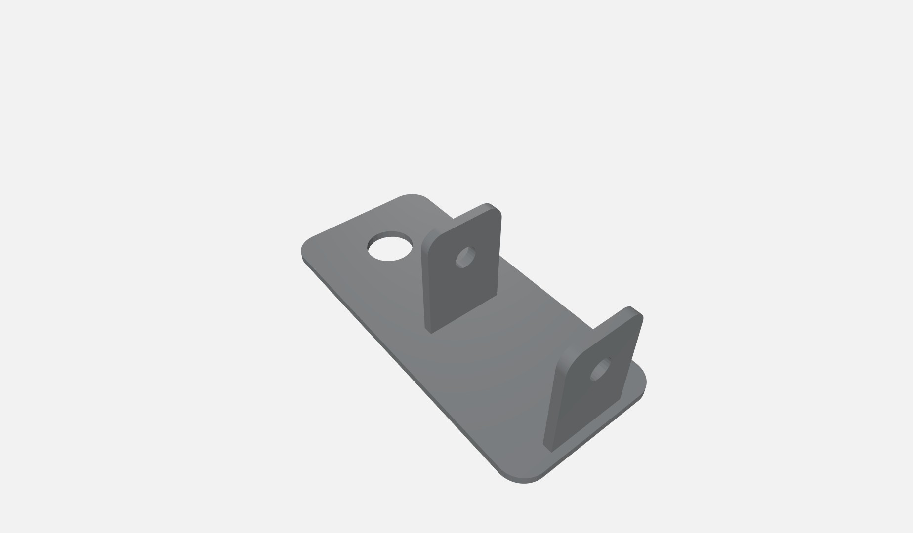
| S01501 | Party ground plate one hole | 8 | 12 | 16 | +2 |
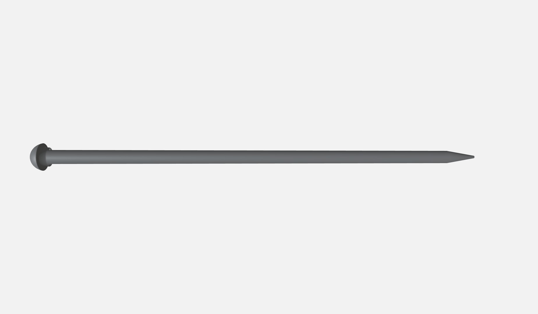
| N29001 | 850mm Stake | 8 | 12 | 16 | +2 |
| S00007 | P-Series 2 Track Side Upright With Eave Insert | 6 | 10 | 14 | +2 |
| S00105 | P6 Rafter 2 Track, with N34013 ridge insert bolted in | 3 | 5 | 7 | +1 |
| S00106 | P6 Rafter 2 Track | 3 | 5 | 7 | +1 |
| N22003 | L pin 12 x 68mm | 11 | 17 | 23 | +3 |
| N22008 | Foot pin 12 x 176mm | 10 | 14 | 18 | +2 |
| D00201 | Flip Cotter (4.5mm linch pin) | 25 | 35 | 45 | +5 |
| S00612 | Party Bar tension 2t eave purlin | 4 | 8 | 12 | +2 |
| S00401 | Party Intermediate Purlin (P-Series, 3m bay) | 6 | 12 | 18 | +3 |
| D11003 | R Clip 3mm | 10 | 18 | 26 | +4 |
| N73010 | Party bar tension eave tensioner assembly | 6 | 10 | 14 | +2 |
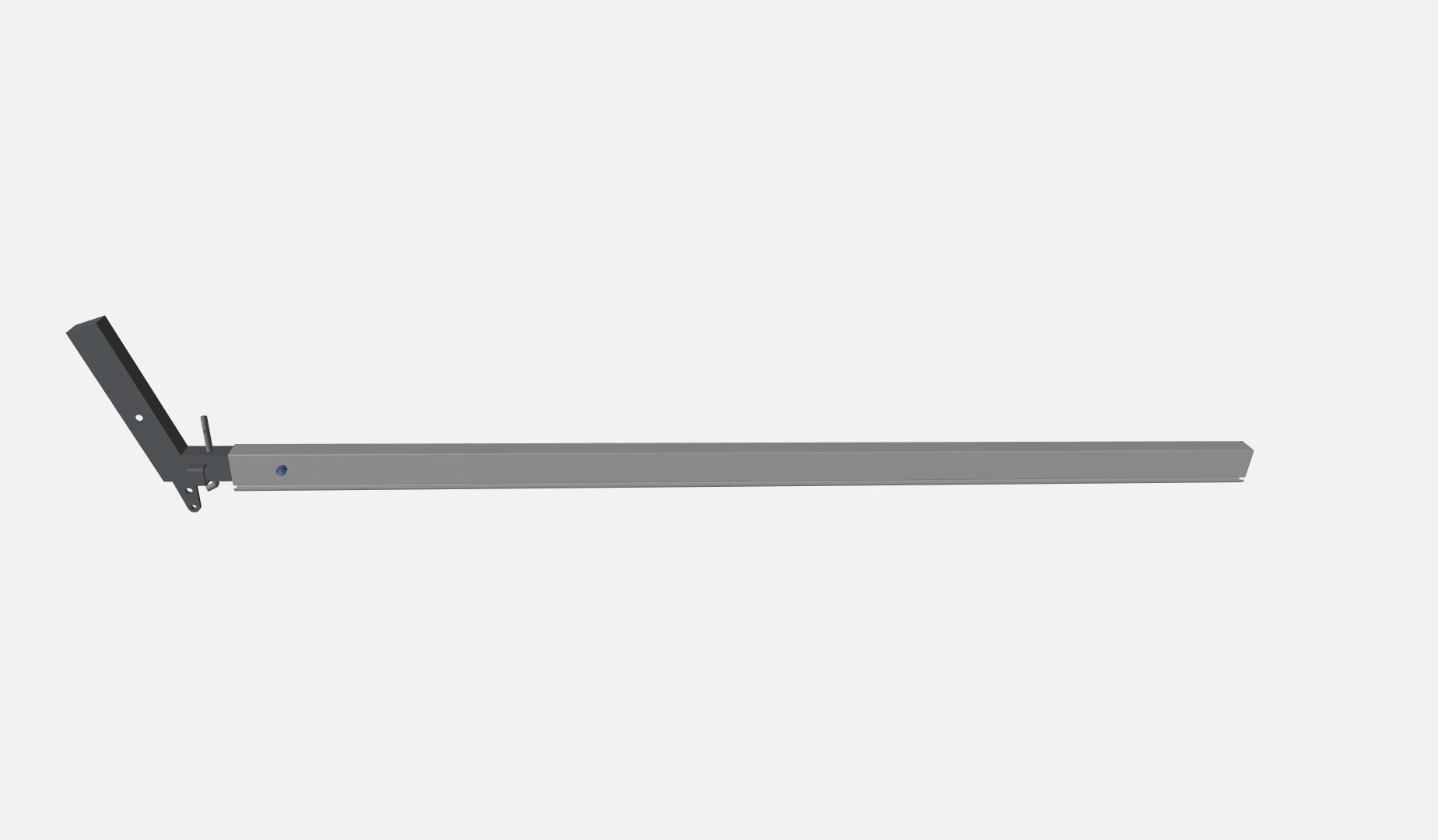
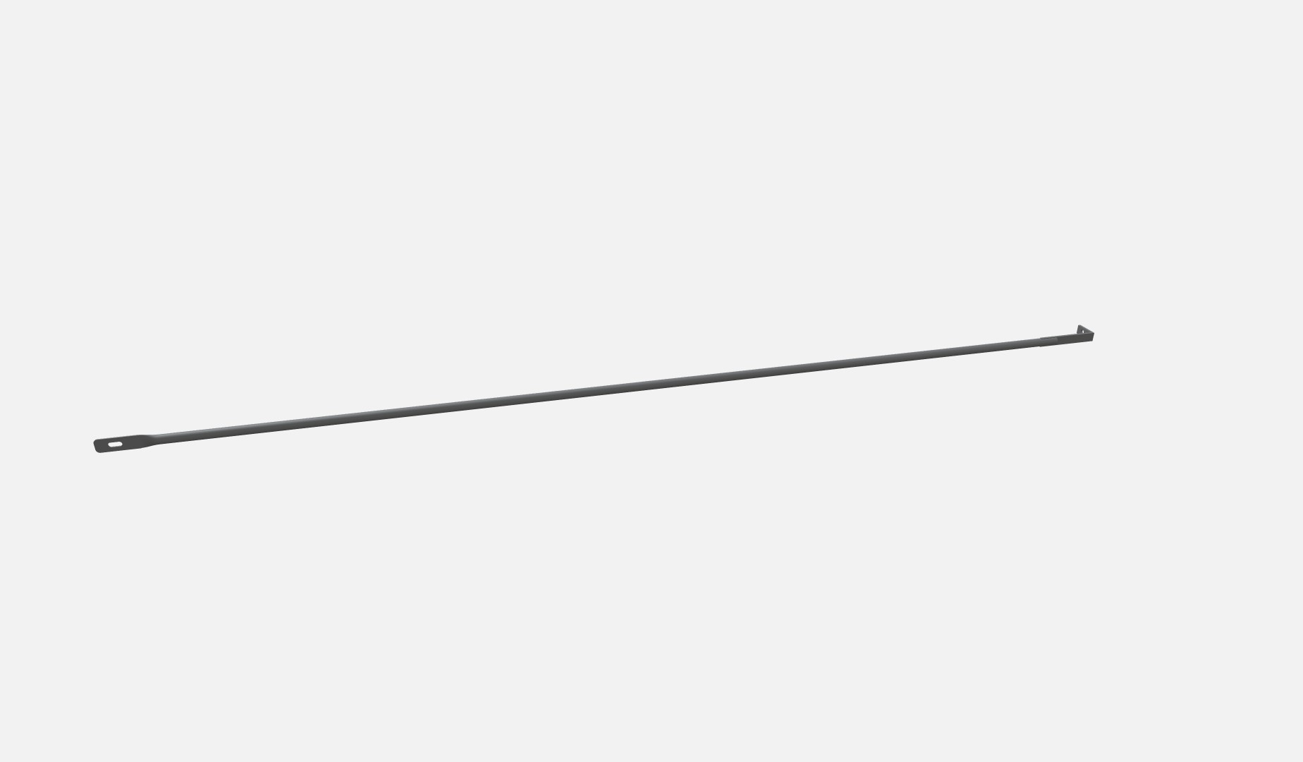
| S01605 | Party diagonal bar 3800mm | 4 | 4 | 4 | – |
| D11001 | R Clip 4mm | 4 | 4 | 4 | – |
| S00382 | P6 Gable Upright 2 track (bar tension) | 2 | 2 | 2 | – |
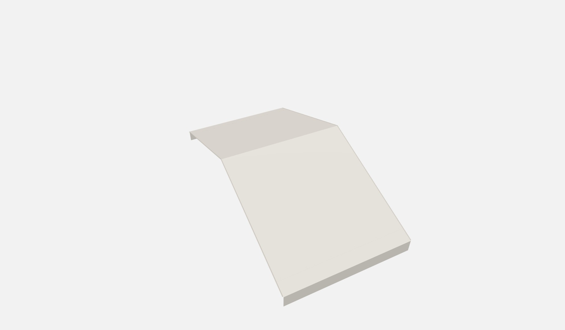
| CP7003 | P6 Roof, bar tension, white, straight valance | 2 | 4 | 6 | +1 |
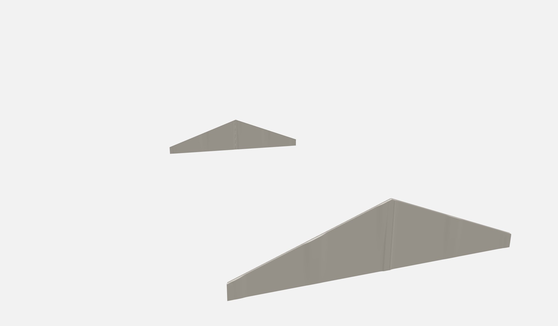
| CP8004 | P6 Gable Set, bar tension, white, laced, straight valance (pair) | 1 | 1 | 1 | – |
| S00613 | P6,9,10,12 Bar tension 2t gable corner purlin | 4 | 4 | 4 | – |
| S01304 | P6, 9, 10, 12 Gable Wall Bar Bottom | 8 | 8 | 8 | – |
| S01201 | Party side wall bar | 8 | 16 | 24 | +4 |
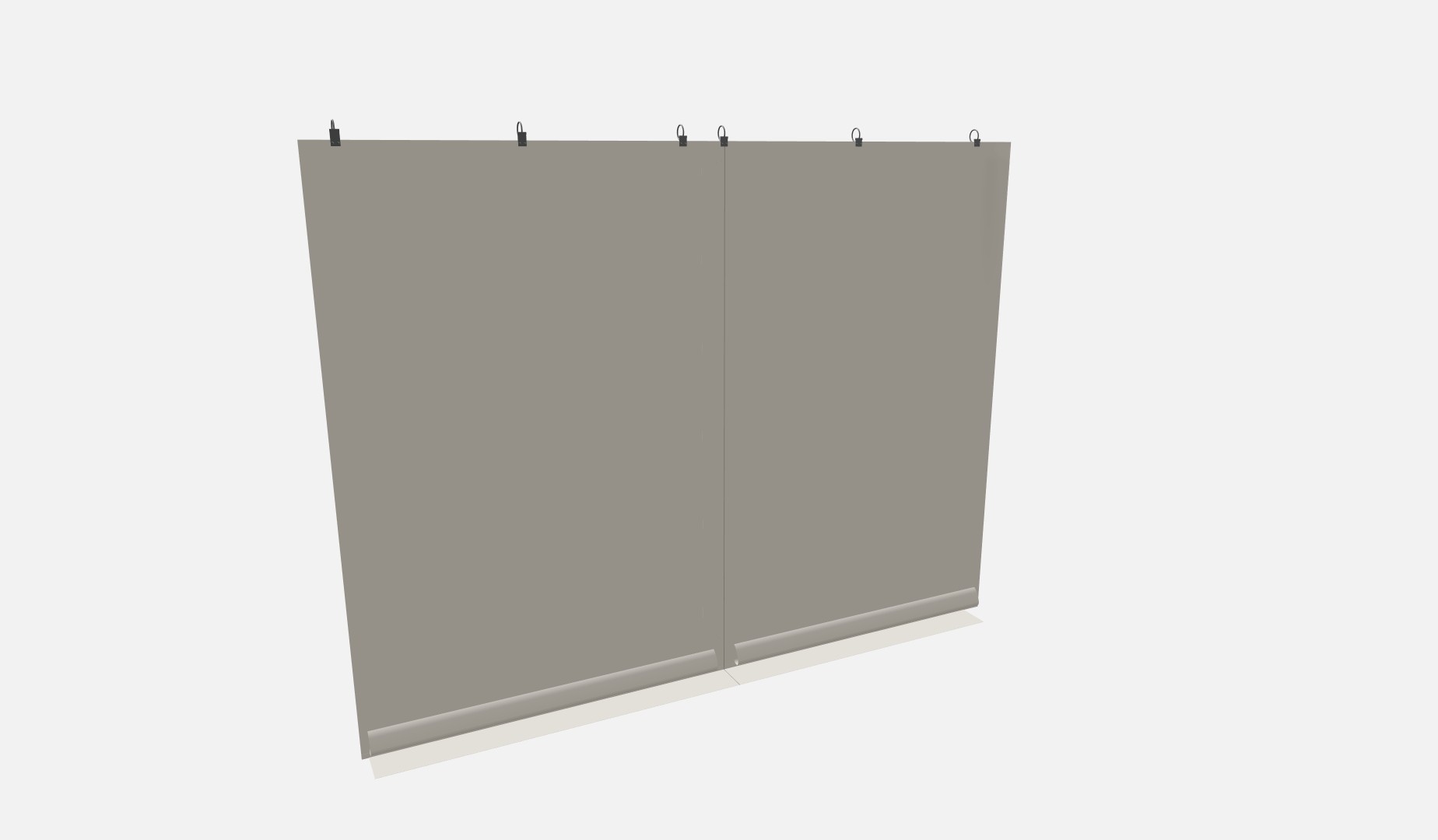
| CP6001 | Party wall, centre laced | 8 | 12 | 16 | +2 |
Supplied assembled, not listed separately: each S00007 with its head bolt and nylock nut; each S00105 left rafter with its N34013 ridge insert, M12 bolt and nylock nut. Carry 10% spare D00201, D11001 and D11003.
Parts identification
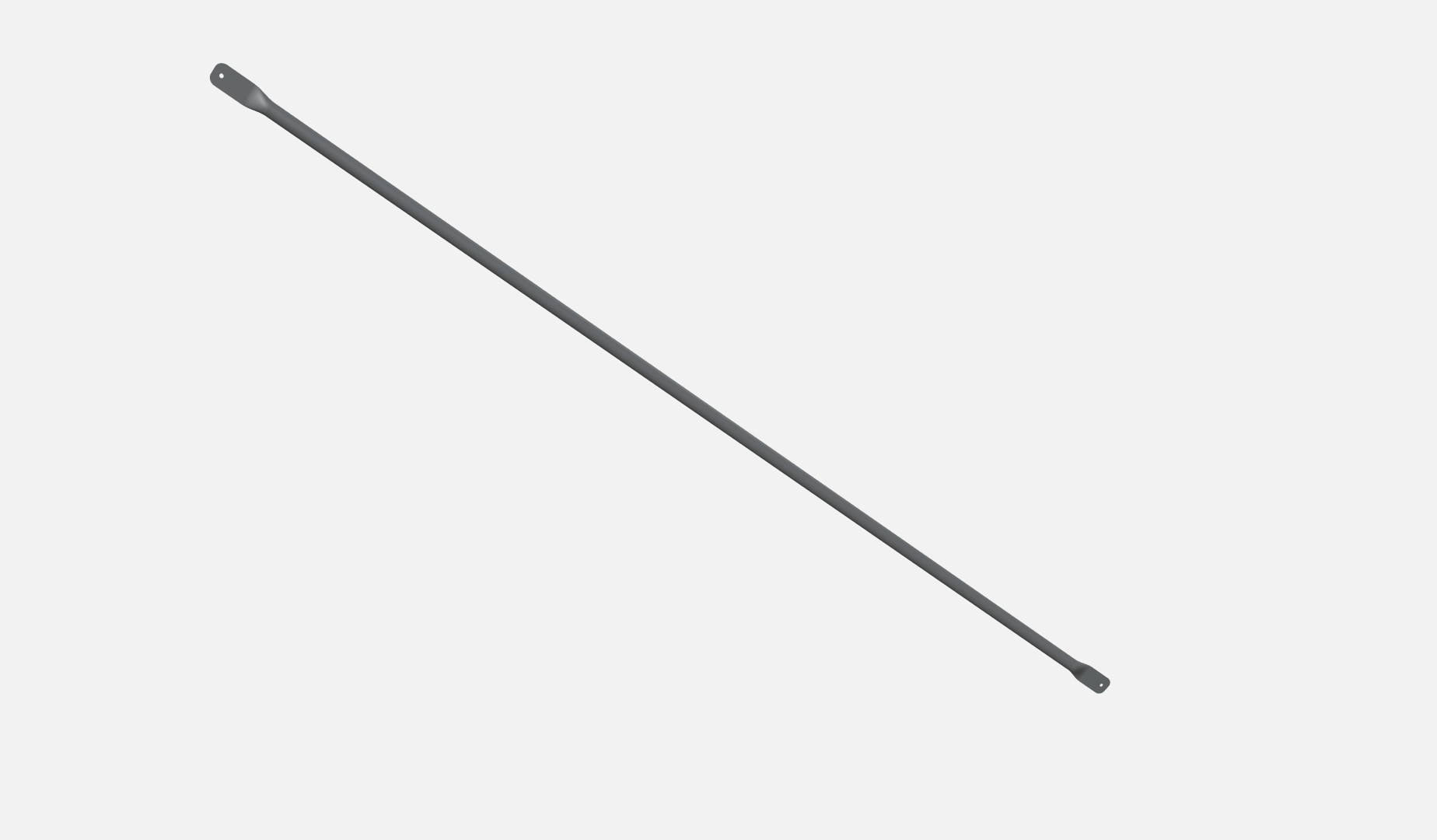
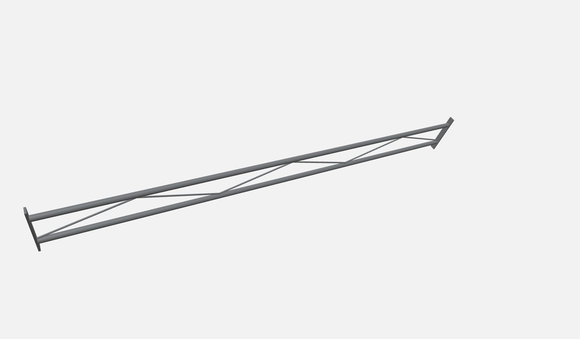
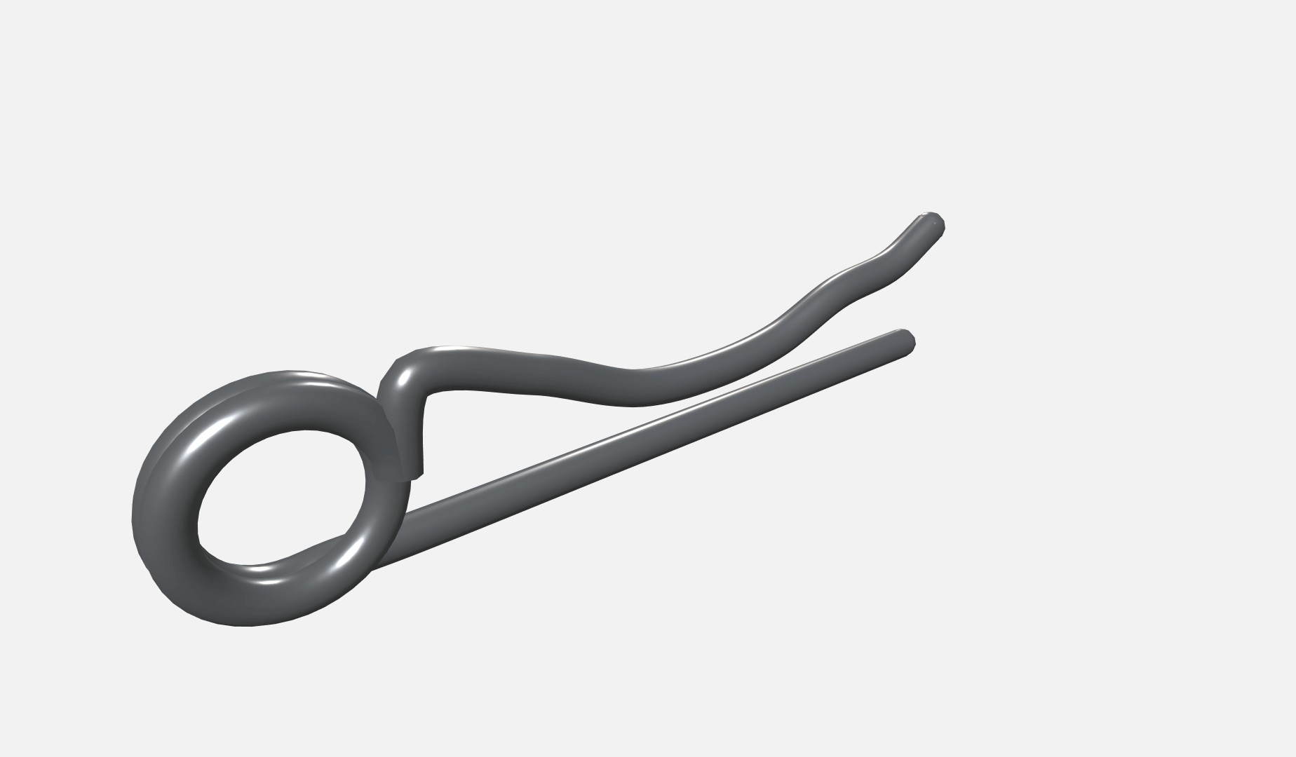
Every component, shown on its own. Long parts are not to scale with small hardware.
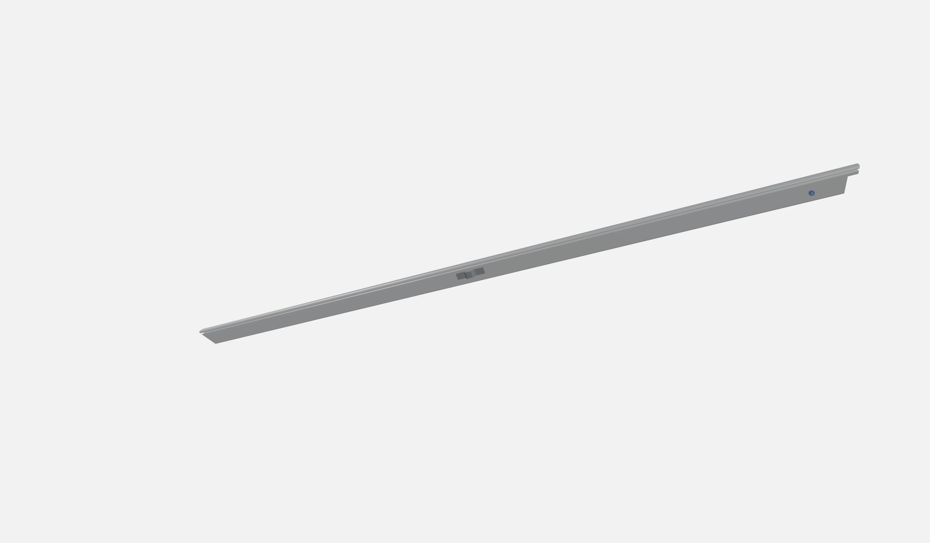
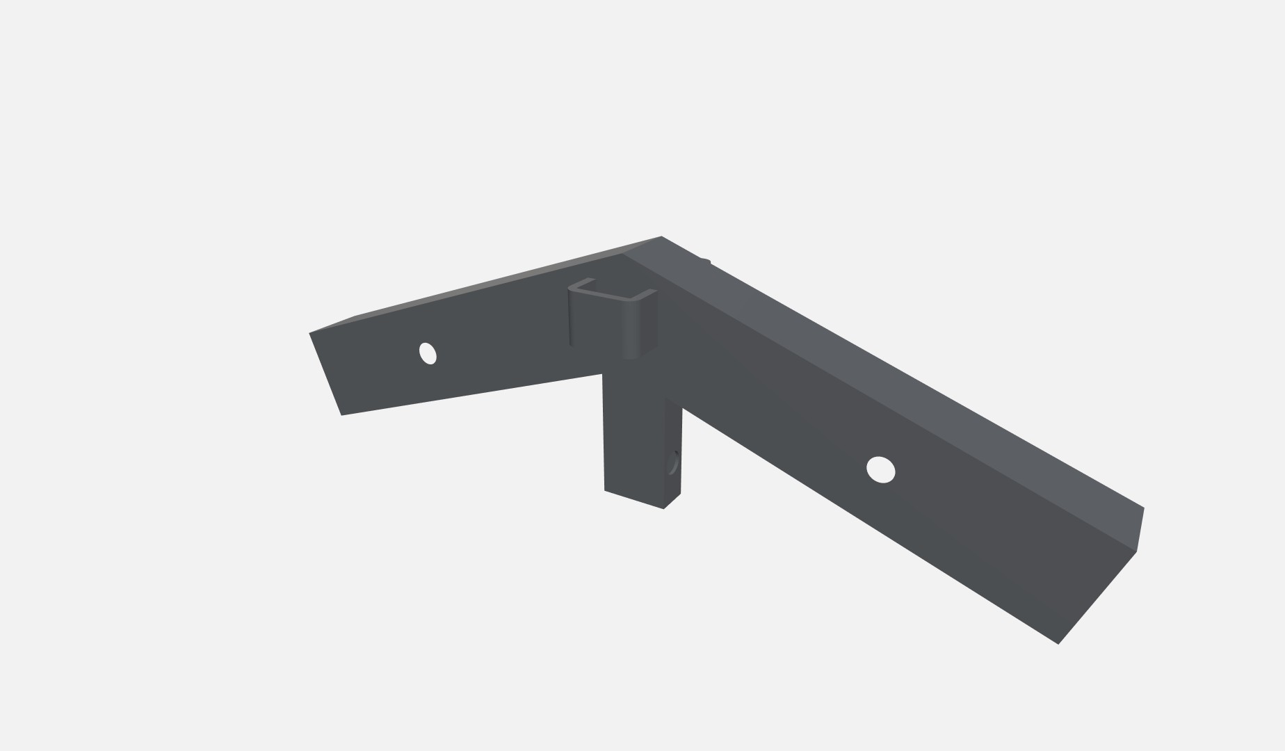
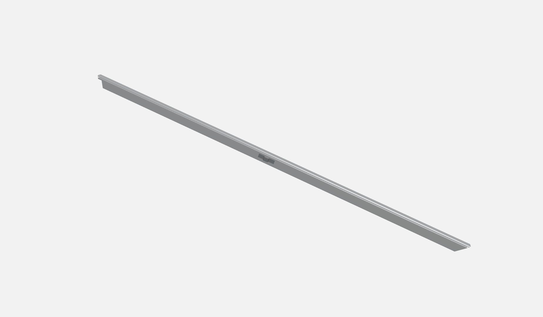
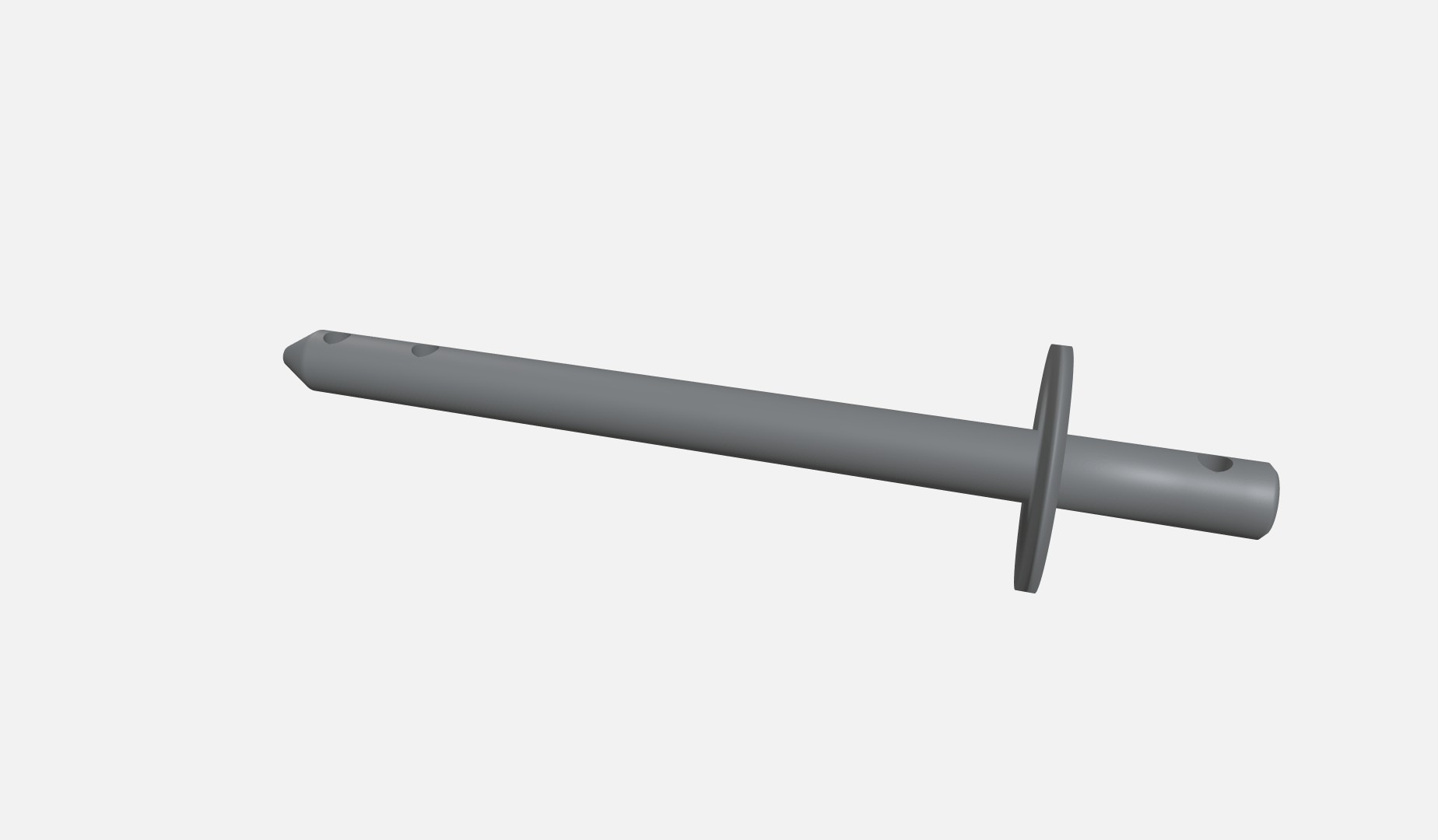
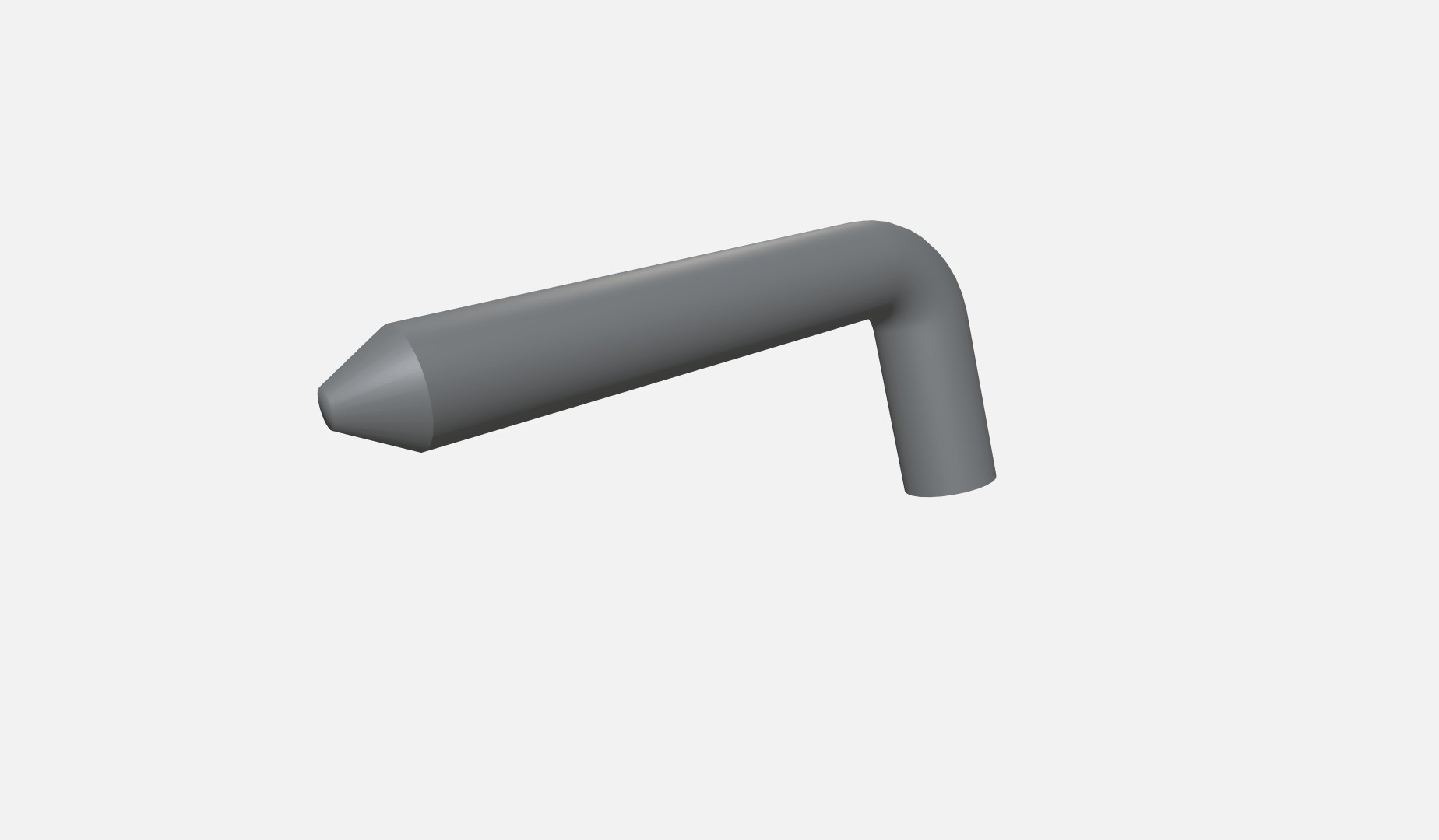
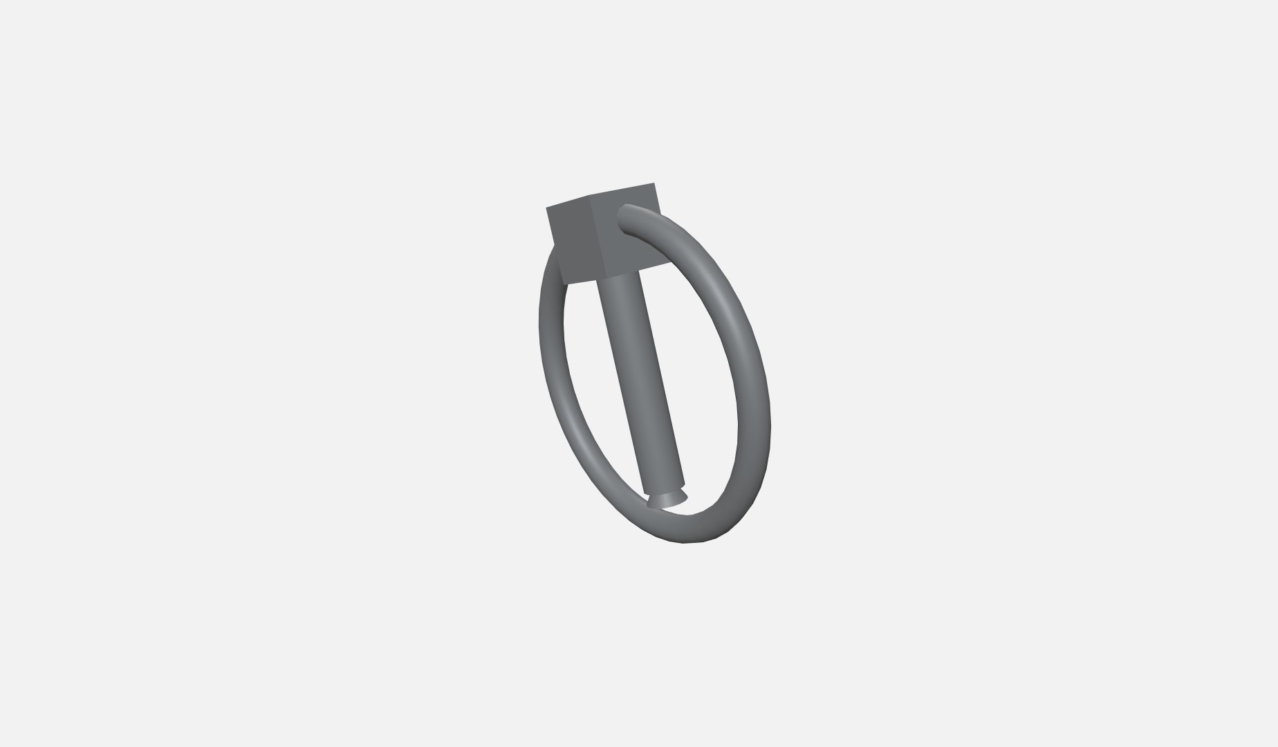
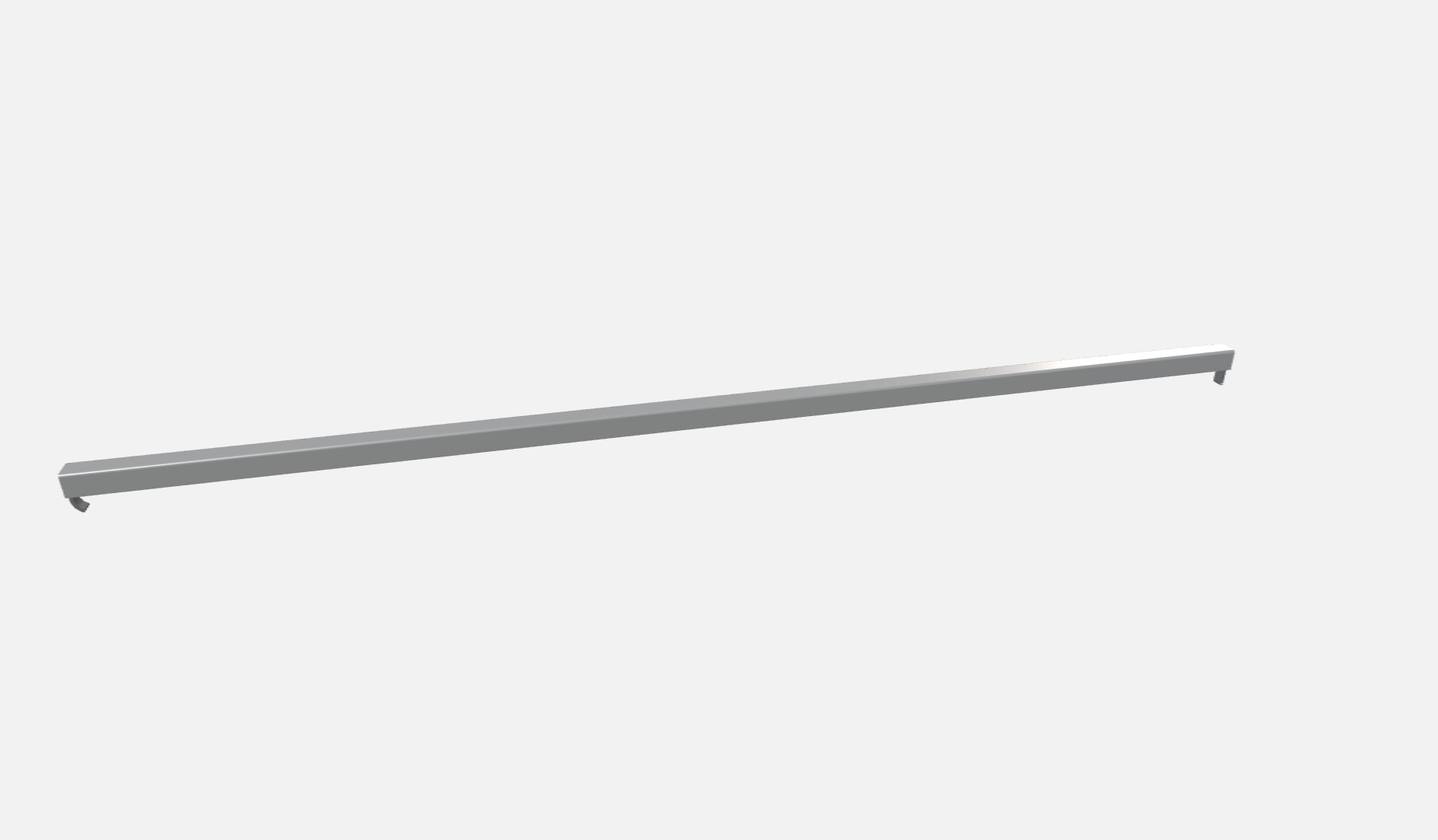
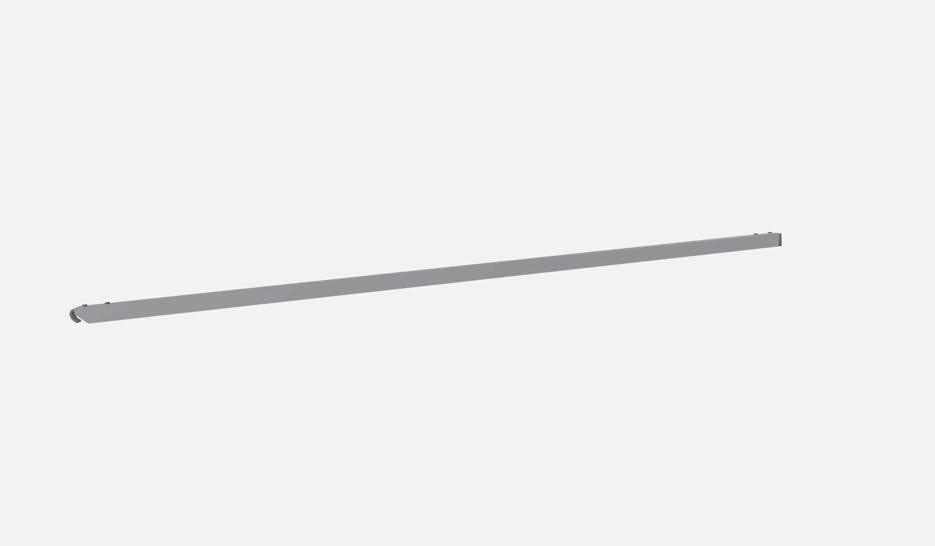
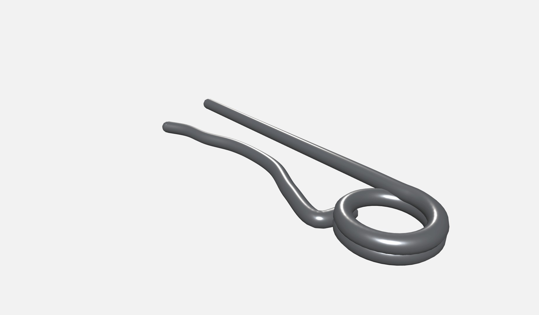
Parts identification, continued
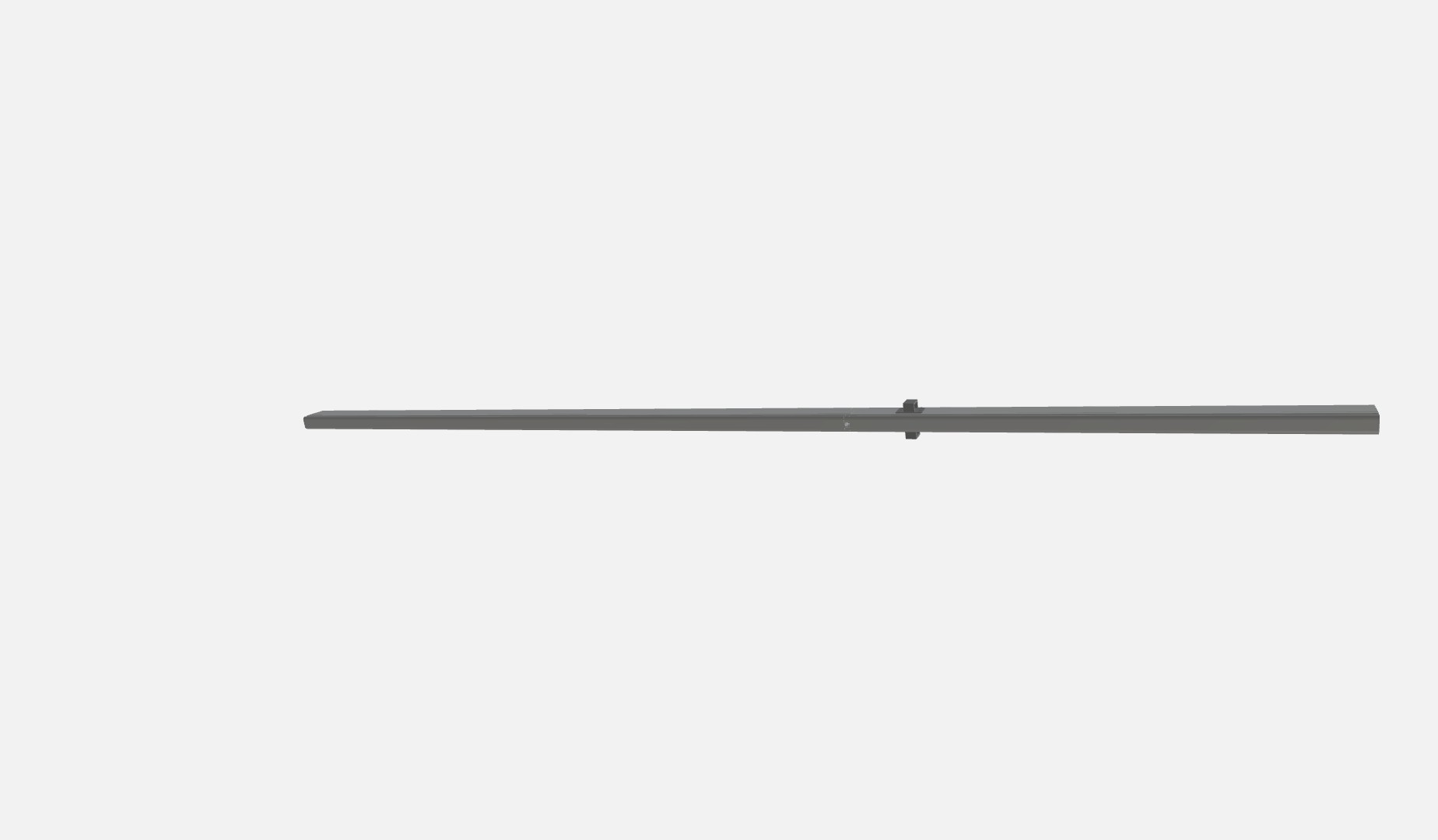
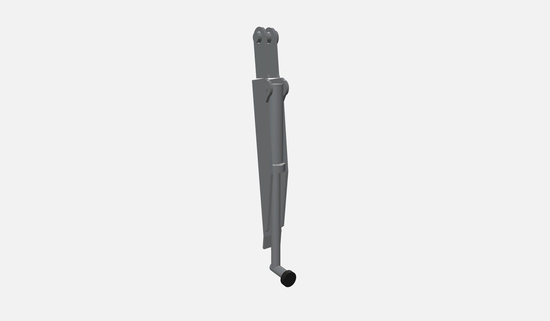
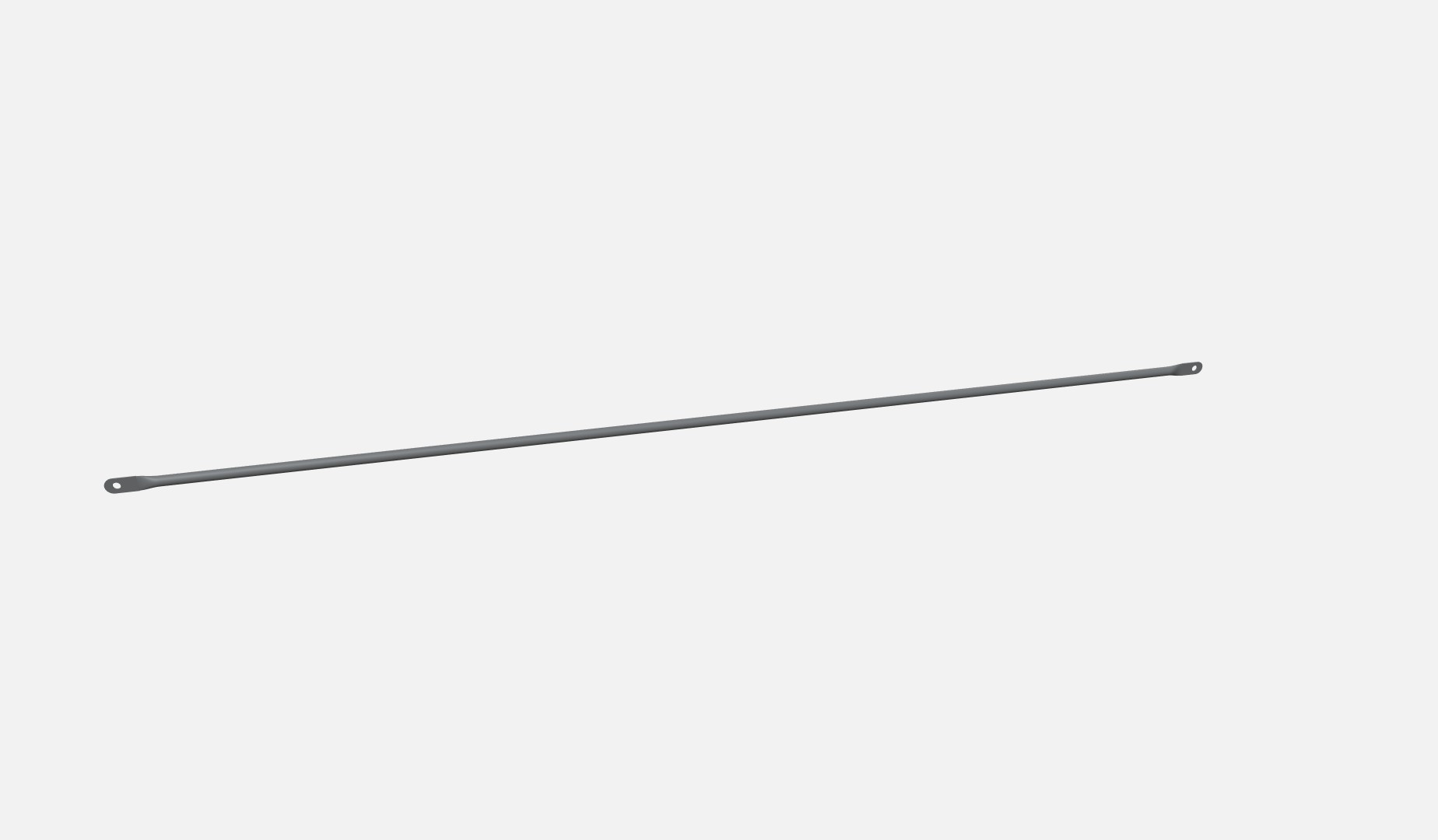
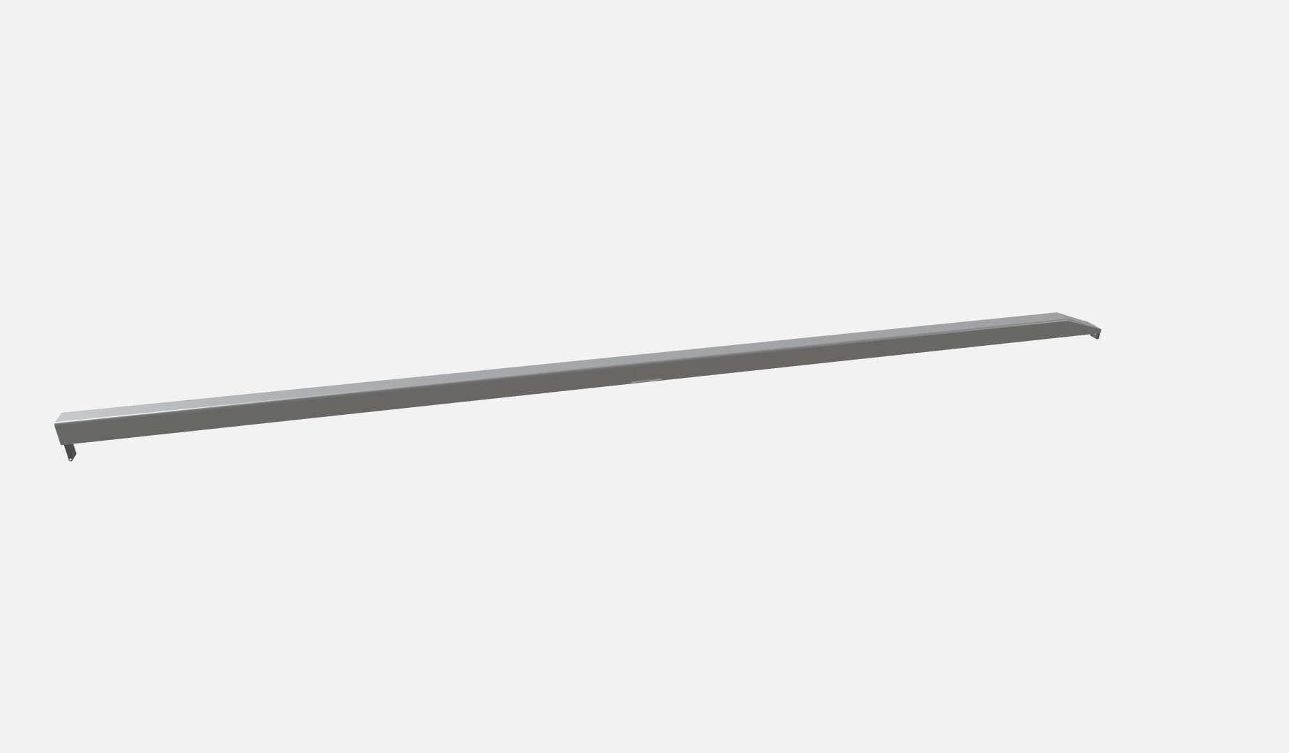
Check the site and set out the ground plates
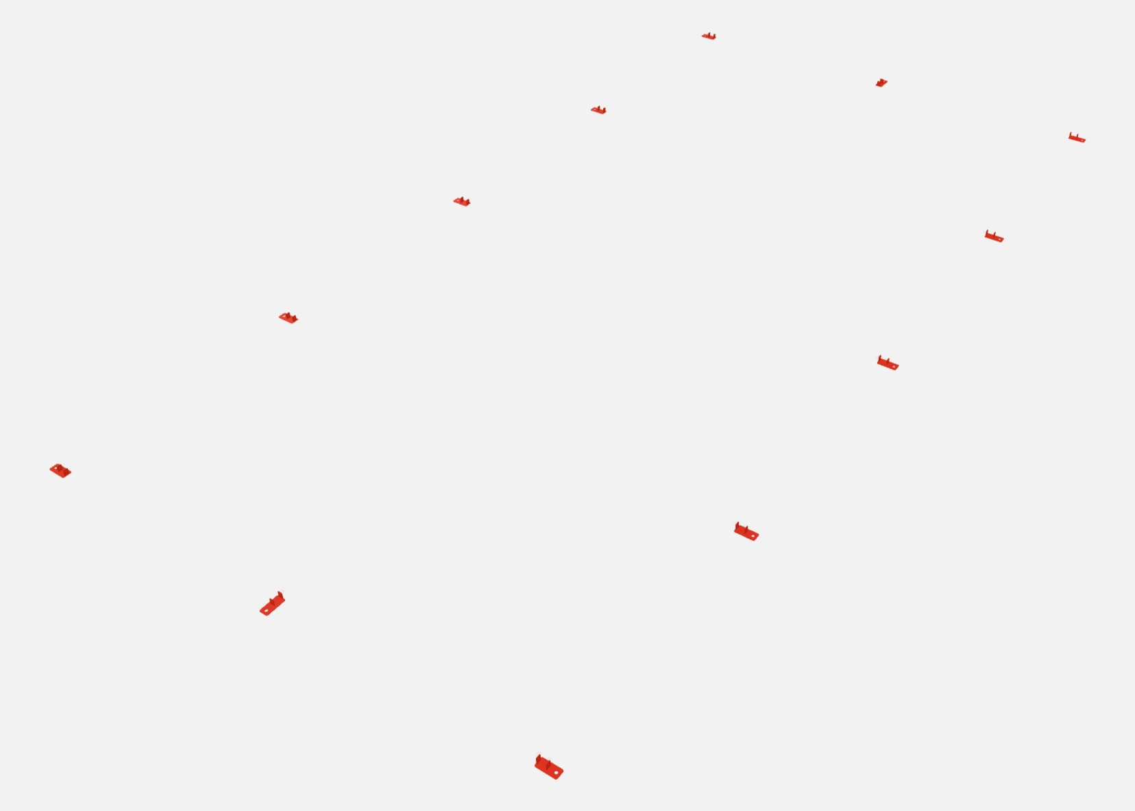
- 1Clear a level area 2000mm longer than the tent and 8000mm wide, and remove stones and debris. All set-out dimensions are to the centre of the S01501 Ground Plate lugs.
- 2Run the first side string line the full tent length. Peg the rear corner plate (A) at the centre of its lugs, then mark a frame line every 3000mm from A.
- 3Square the rear gable line off the side line with the 3-4-5 method (see Squaring with the 3-4-5 method). Peg the opposite rear corner plate (B) 5896mm from A.
- 4Peg each plate on the opposite side: 3000mm from the previous peg on that side, and the diagonal from A in the table. Peg where the two tapes meet.
- 5Peg a gable centre plate on each gable line, 2948mm from both side lines.
- 6Lay an S01501 centred on every peg, lugs on the line, stake hole pointing outward.
Squaring with the 3-4-5 method
A triangle with sides of 3000, 4000 and 5000mm always has a right angle between the 3000 and 4000mm sides. Use it to set the rear gable line at exactly 90° to the side line. You need three people and two tapes.
- 1At the rear corner peg (A), measure 3000mm along the side string. This is the frame line 2 peg.
- 2Person 1 holds the zero of tape one on A. Person 2 holds the zero of tape two on the 3000mm peg.
- 3Person 3 takes the 4000mm mark of tape one and the 5000mm mark of tape two and brings them together across the gable side. Pull both tapes taut and peg where the marks meet (C).
- 4The line from A through C is the rear gable line, square to the side. Sight along it and peg the opposite rear corner (B) 5896mm from A.
- 5Set every other plate on B’s side from A with the diagonal table.
Diagonal from A to each plate on the opposite side
Top: distance along the side from the rear gable line (mm). Bottom: diagonal from A (mm). All to the centre of the S01501 ground plate lugs.
Measure every diagonal from the same point: the centre of the lugs on plate A, to the centre of the lugs on each plate. Pull the tapes tight and keep them level, not draped over the grass.
Stake the ground plates
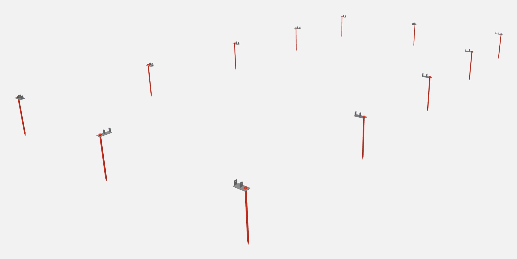
- 1Re-check every plate against the diagonal table before driving anything home.
- 2Drive one N29001 850mm Stake through the hole in each ground plate until the domed head and collar seat on the plate.
- 3If a stake hits an obstruction, stop. Move the plate along the line by no more than 50mm, re-measure and try again.
Assemble every span (A-Frame) flat on the ground
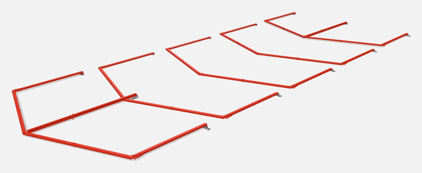
- 1Assemble every span (A-Frame) flat at its frame line, ridge towards the front, before standing any up. The front gable span lies outside the tent.
- 2Pin the first S00007 Side Upright with Eave Insert to its ground plate with an N22008 Foot Pin (washer inside) and a D00201 Flip Cotter in the outer hole.
- 3Attach the S00105 Rafter with Ridge Insert to that upright’s eave insert with an N22003 L Pin and D00201.
- 4Slide the S00106 Rafter onto the ridge insert and secure it with an N22003 L pin and D00201.
- 5Attach the second upright to the S00106 eave end with an N22003 and D00201, then pin its foot as the first. Check both factory-fitted head bolts are tight.
- 6Fit an N73010 eave tensioner to the link tab on each S00007 eave insert: hinge pin through the fork and tab, locked with a D11003 3mm R Clip. Leave the lever open.
- 7Gable spans only: pin an S00382 Gable Upright 2 track (bar tension) into the N34013 Ridge Insert drop box with an N22003 and D00201, tracks facing out. Leave the foot free until the span is stood up.
- 8Push an N22008 through the Ø13 hole 2085 up the S00382, from the inside of the marquee out, washer on the inside. Fit a D00201 in the outermost hole, on the outside of the marquee.
Raise Span 1 (A-Frame) on temporary braces
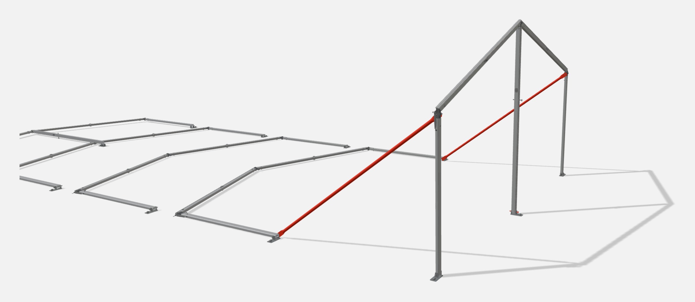
- 1The spans (A-Frames) are already pinned to the ground plates and hinge on the pins.
- 2On each side, slide the S01605 Diagonal Bar bottom tongue onto the inside end of the frame line 2 foot pin and lock it with a D00201 Flip Cotter in the inner hole.
- 3A and B, one at each side upright, lift the span (A-Frame) by hand and pivot it up on the foot pins to vertical.
- 4A and B hold it vertical. C and D, one per side, lift the S01605 and hook its top tongue onto the eave insert pin of the Span 1 S00007 Side Upright with Eave Insert. Lock it with a D11001 4mm R Clip.
- 5Pin the S00382 Gable Upright 2 track (bar tension) foot to the gable centre plate with an N22008 Foot Pin (washer inside) and a D00201 in the outer hole.
- 6The braces hold Span 1 (A-Frame) securely while the rest of the frame is built. They are rotated into their final position in step 09.
Raise Span 2 (A-Frame) and fit the bay 1 purlins
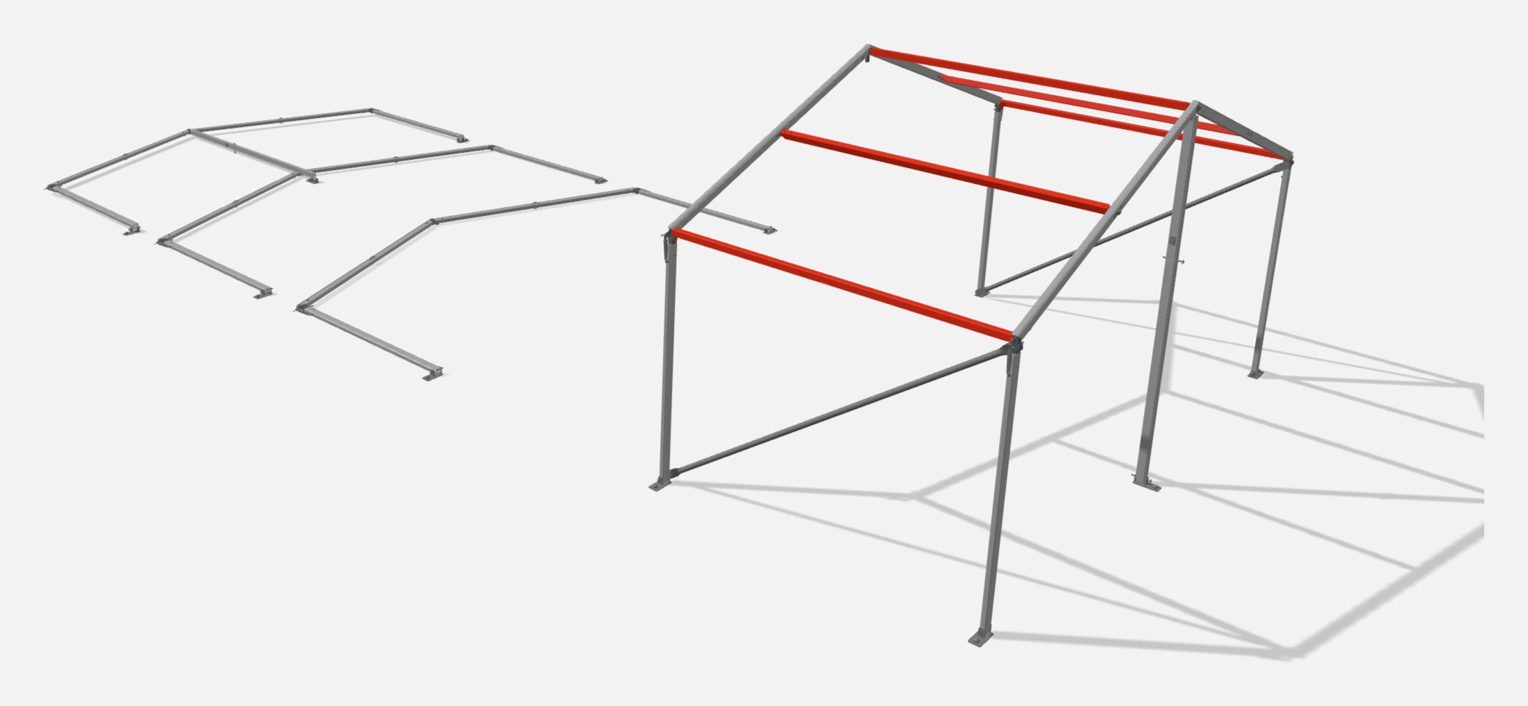
- 1The span (A-Frame) is already pinned to the ground plates and hinges on the pins. A and B, one at each side upright, lift and pivot it up by hand to vertical.
- 2A and B hold the span (A-Frame) vertical. C and D fit the two S00612 Eave Purlins by hand between Spans (A-Frames) 1 and 2: curved hook end in first, then the straight bracket end. Fit a D11003 3mm R Clip through each straight end so it cannot lift out.
- 3One person fits the three S00401 Purlins (two intermediate, one ridge) with the purlin fork: hook the curved end into the rafter or ridge insert bracket first, then lift and pivot the purlin up with the fork and hook the straight angle end into the opposite bracket.
- 4Bay 1 is now tied in.
Central bays: raise the next span (A-Frame) and fit its bay purlins
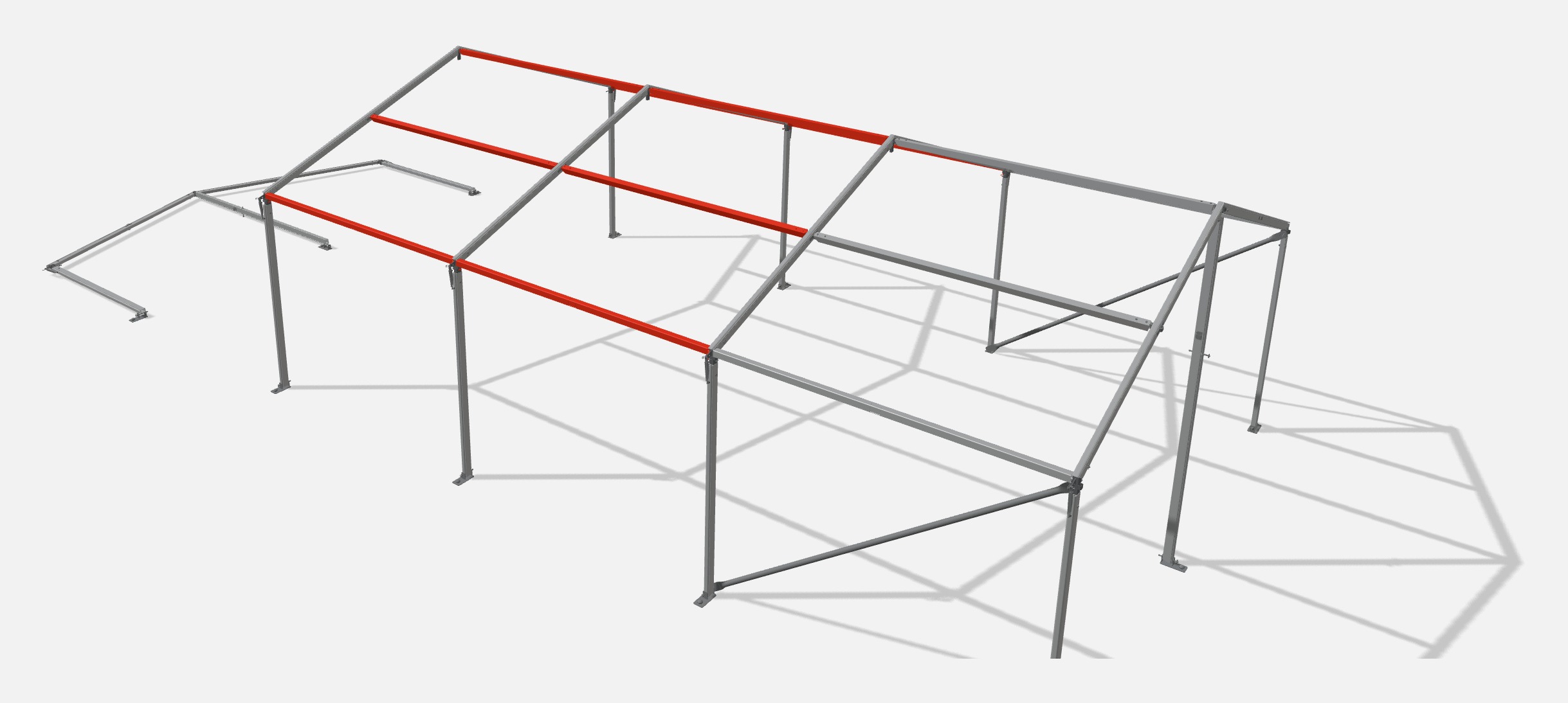
- 1The span (A-Frame) is already pinned to the ground plates and hinges on the pins. A and B, one at each side upright, lift and pivot it up by hand to vertical.
- 2A and B hold the span (A-Frame) vertical. C and D fit the two S00612 Eave Purlins by hand between the previous span (A-Frame) and this one: curved hook end in first, then the straight bracket end. Fit a D11003 3mm R Clip through each straight end so it cannot lift out.
- 3One person fits the three S00401 Purlins (two intermediate, one ridge) with the purlin fork: hook the curved end into the rafter or ridge insert bracket first, then lift and pivot the purlin up with the fork and hook the straight angle end into the opposite bracket.
- 4Release the span only once all its purlins are in. Repeat this step once for each central bay: none for a 6 m tent, one for 9 m, two for 12 m, four for 18 m.
Raise the front gable span (A-Frame) and fit the last bay purlins
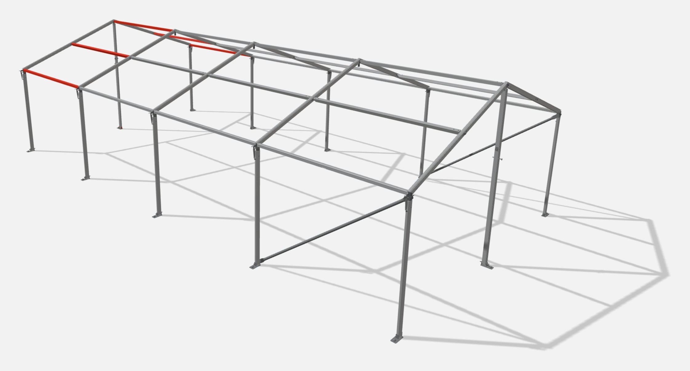
- 1The span (A-Frame) is already pinned to the ground plates and hinges on the pins. A and B, one at each side upright, lift and pivot it up by hand to vertical.
- 2A and B hold the span (A-Frame) vertical. C and D fit the two S00612 Eave Purlins by hand between the last central span (A-Frame) and the front gable span: curved hook end in first, then the straight bracket end. Fit a D11003 3mm R Clip through each straight end so it cannot lift out.
- 3One person fits the three S00401 Purlins (two intermediate, one ridge) with the purlin fork: hook the curved end into the rafter or ridge insert bracket first, then lift and pivot the purlin up with the fork and hook the straight angle end into the opposite bracket.
- 4Pin the S00382 Gable Upright 2 track (bar tension) foot to the front centre plate with an N22008 Foot Pin (washer inside) and a D00201 Flip Cotter in the outer hole.
- 5Keep two people steadying the front gable span until the last bay is braced.
Brace the last bay
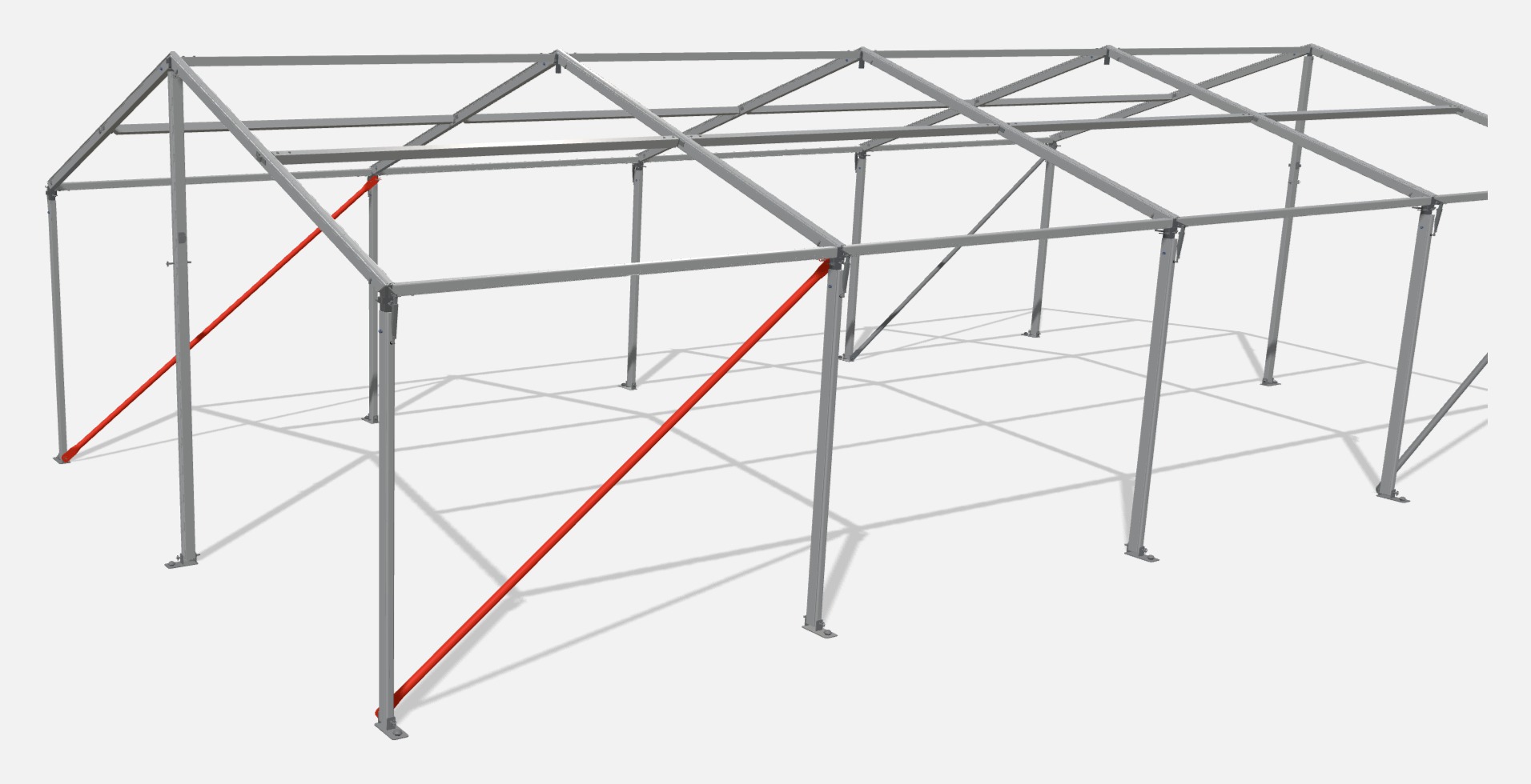
- 1On each side, inside face: hook the S01605 Diagonal Bar top tongue onto the eave insert pin of the S00007 Side Upright with Eave Insert on the span (A-Frame) next to the front gable. Lock it with a D11001 4mm R Clip.
- 2Drop the bottom tongue onto the front gable foot pin, against the washer. Fit a D00201 Flip Cotter in the inner hole.
- 3Check the last bay floor diagonals: 6615mm each.
Rotate the bay 1 braces into position
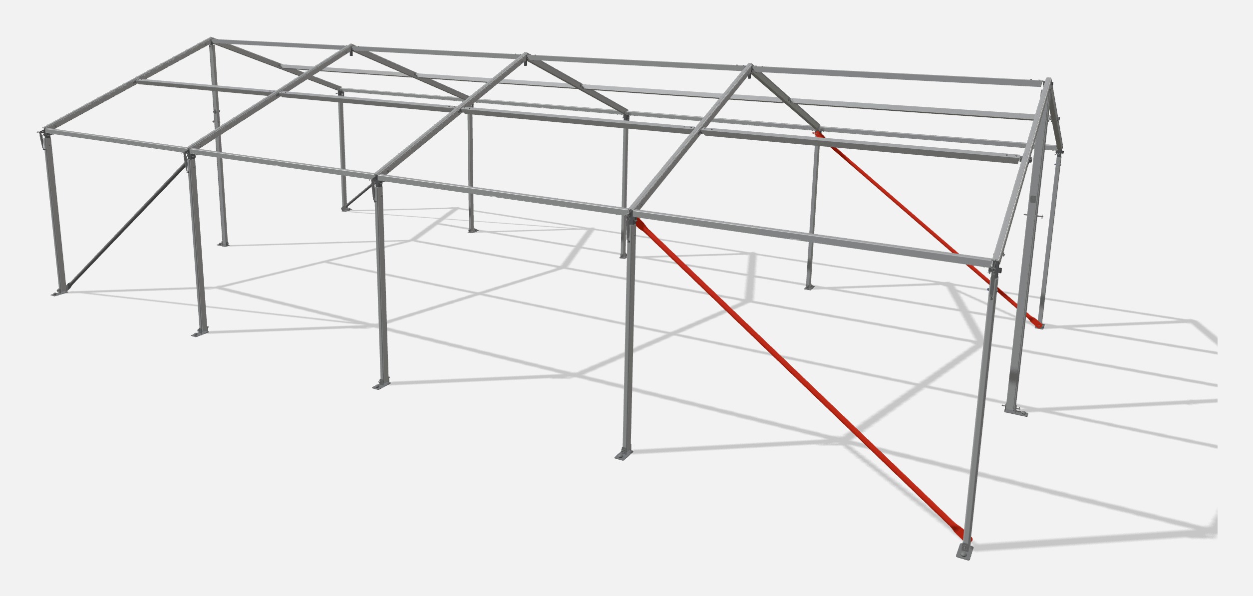
- 1With the rest of the frame built and the last bay braced, go back to bay 1. Work one side at a time.
- 2Unclip the S01605 Diagonal Bar top from the Span 1 (A-Frame) insert pin. Remove the D00201 Flip Cotter at the frame line 2 foot pin and slide the brace foot off.
- 3Rotate the brace end for end. Hook its top tongue onto the eave insert pin of the Span 2 (A-Frame) S00007 Side Upright with Eave Insert and lock it with the D11001 4mm R Clip.
- 4Drop the bottom tongue onto the Span 1 (A-Frame) foot pin, against the washer, and lock it with the D00201 in the inner hole.
Check the frame
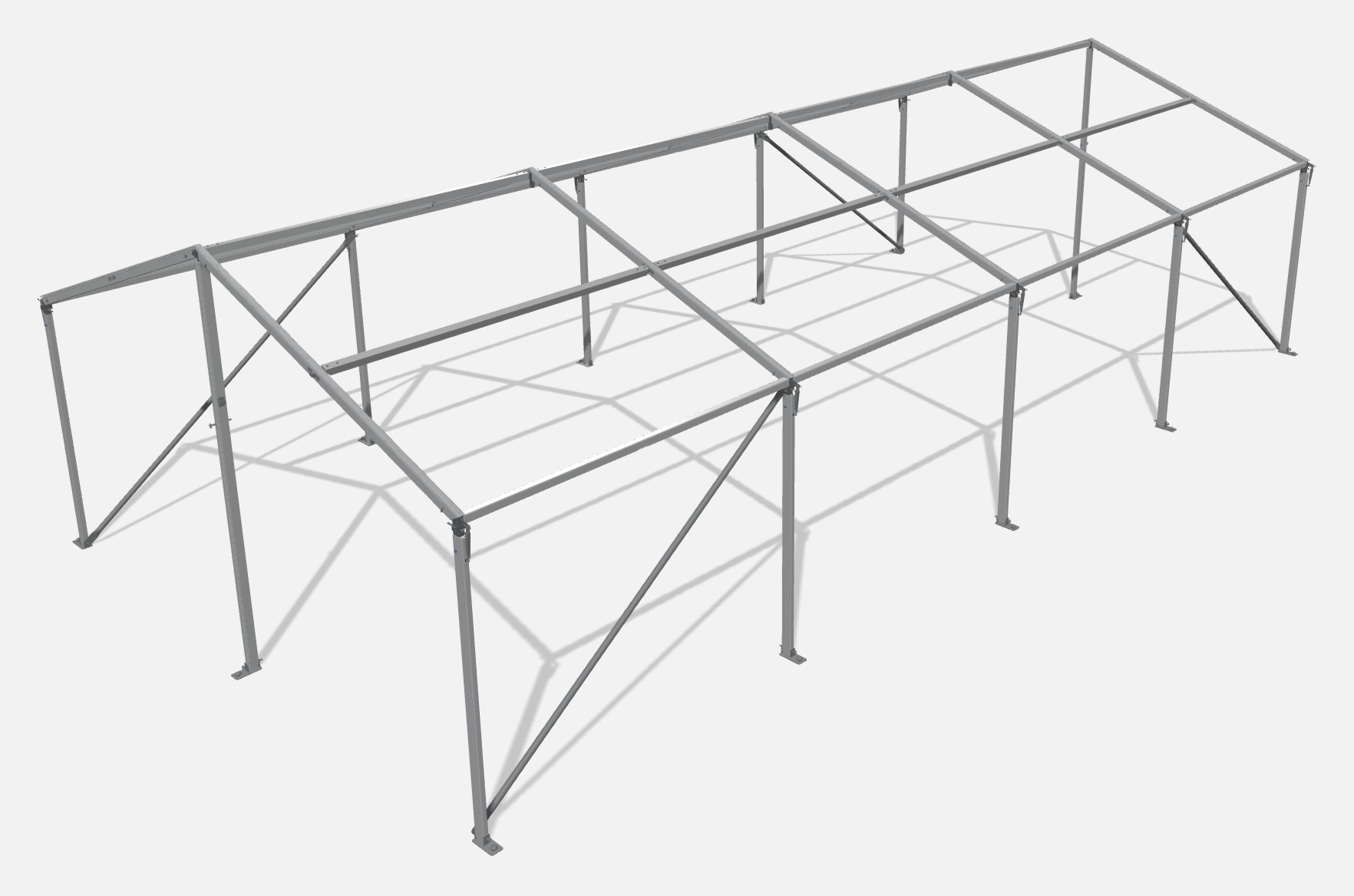
- 1Walk round. Every foot pin has its D00201 Flip Cotter, every rafter joint has its pin, every eave purlin has its D11003 3mm R Clip.
- 2All stakes are seated, all legs plumb, and the ridge is straight by eye.
- 3Optional: if an S01701 portal brace is being fitted in place of the left-side S01605 Diagonal Bar in bay 1, fit it now, before the covers. See “Optional: S01701 portal brace”.
Pull the roof covers through
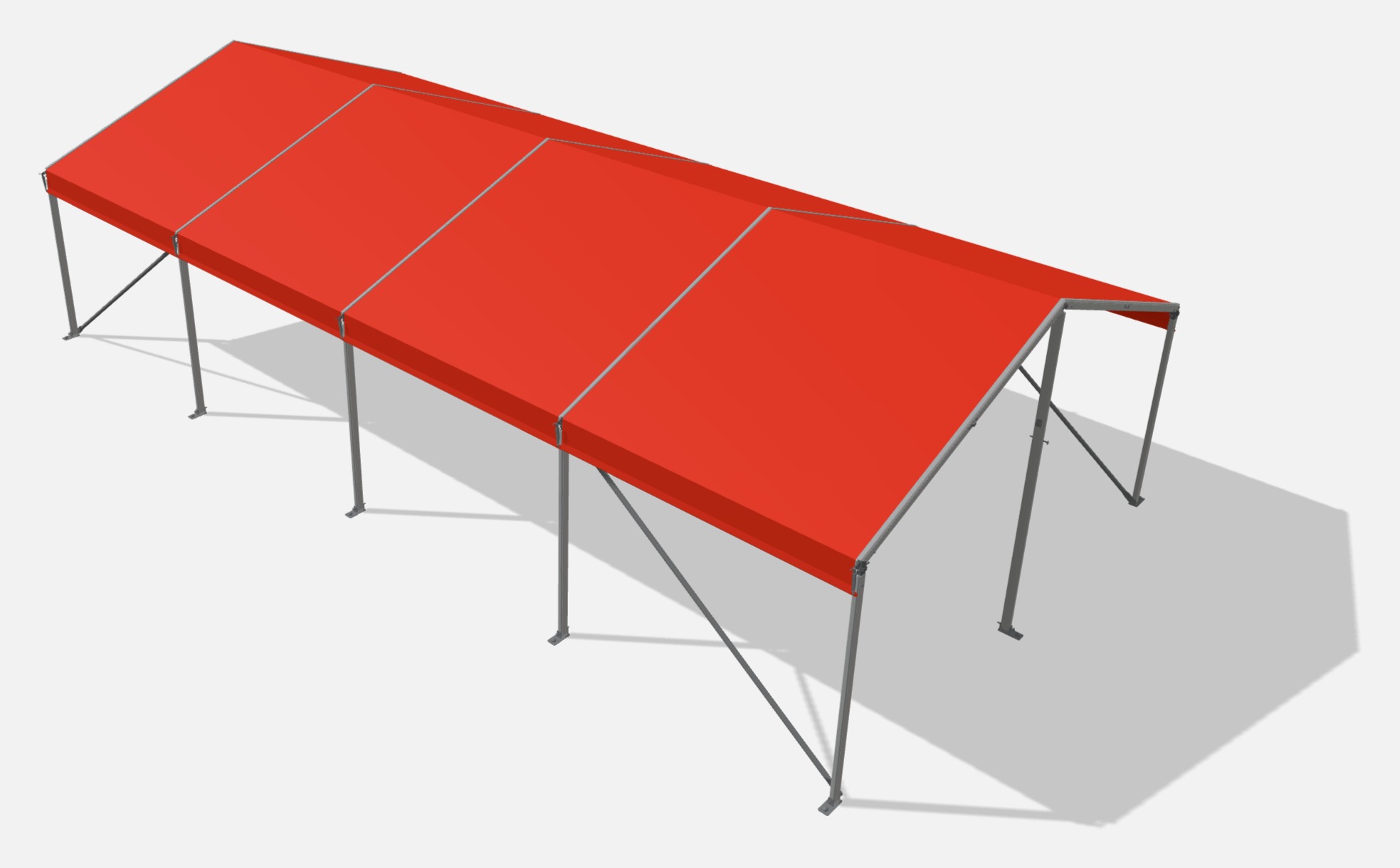
- 1Start at the rear bay. Lay a folded CP7003 Roof Cover along the left-side eave, outer face up.
- 2A and B feed both keder edges into the rafter tracks at the eave of each span (A-Frame).
- 3C and D, on the other side, pull the roof up over the ridge and down to the opposite eave with the two roof pulling ropes, one at each rafter. A and B keep feeding so it runs straight.
- 4Centre the roof so the valance hangs evenly at both eaves. Repeat for every bay, rear to front.
- 5At each eave, slide an S01201 Side Wall Bar through the pocket in the bottom of the CP7003 valance. Hook both ends onto the N73010 eave tensioner foot bars, just behind the washer. Neighbouring bays share each tensioner, tongues side by side.
- 6Close each N73010 lever down against the S00007 Side Upright with Eave Insert to pull the roof down taut.
Fit the gable triangles
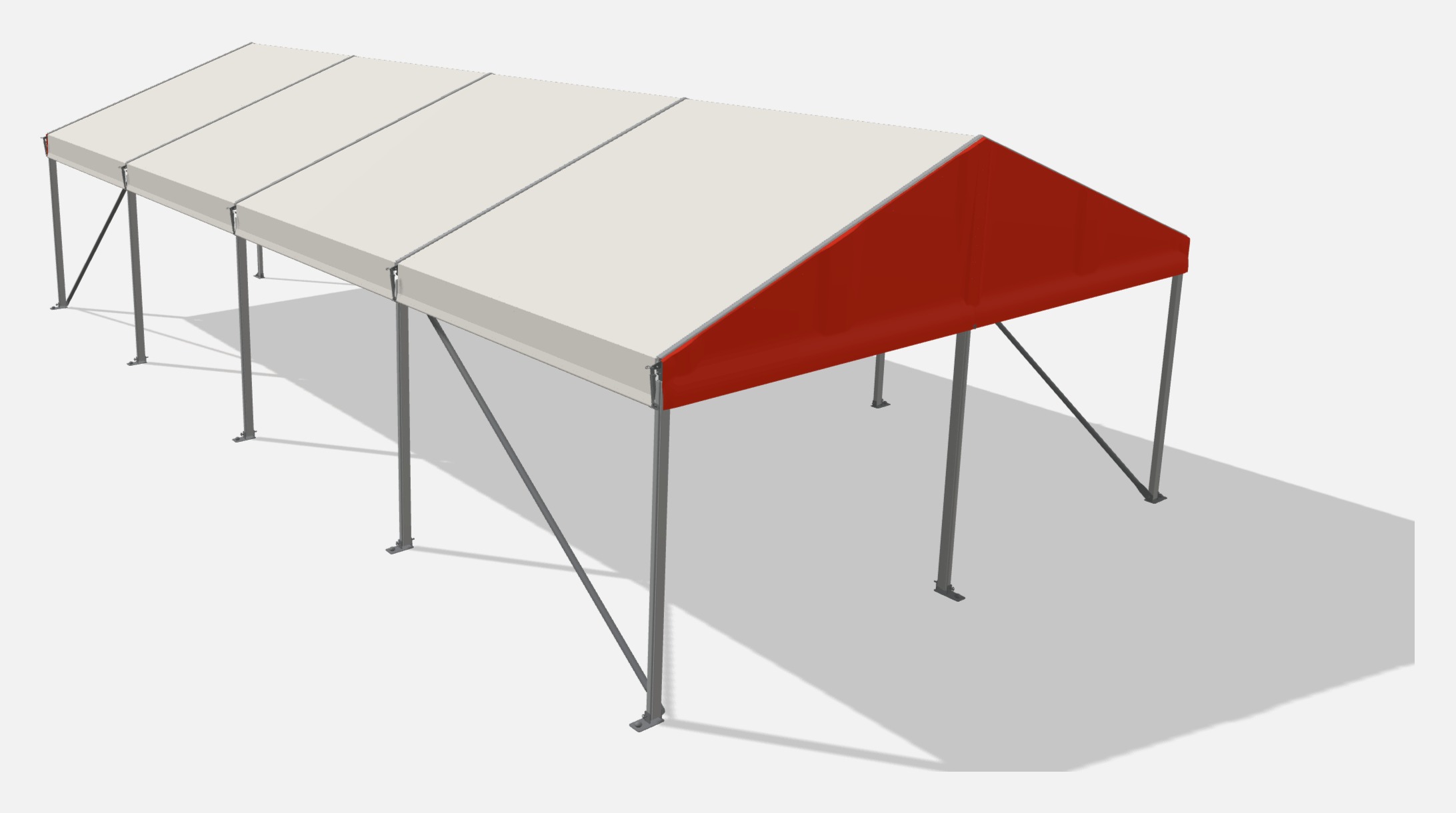
- 1At each end, feed the triangle keder into the outer track of both gable rafters, eave to ridge.
- 2Working from a stepladder, do up the Dutch lacing on the centre seam over the S00382 Gable Upright 2 track (bar tension), from the ridge down.
- 3The valance hangs straight across the gable, level with the roof valance.
- 4Slide an S01304 Gable Wall Bar Bottom through the pocket along each side of the CP8004 Gable Triangle Set valance. Hook its slot onto the N22008 Foot Pin at 2085 on the S00382 (through the Ø15 hole in the CP8004), outside the washer and inside the D00201 Flip Cotter.
- 5Hook the turned tab round the corner leg onto the N73010 foot bar, then close the N73010 lever to tension the gable triangle.
Hang the gable walls
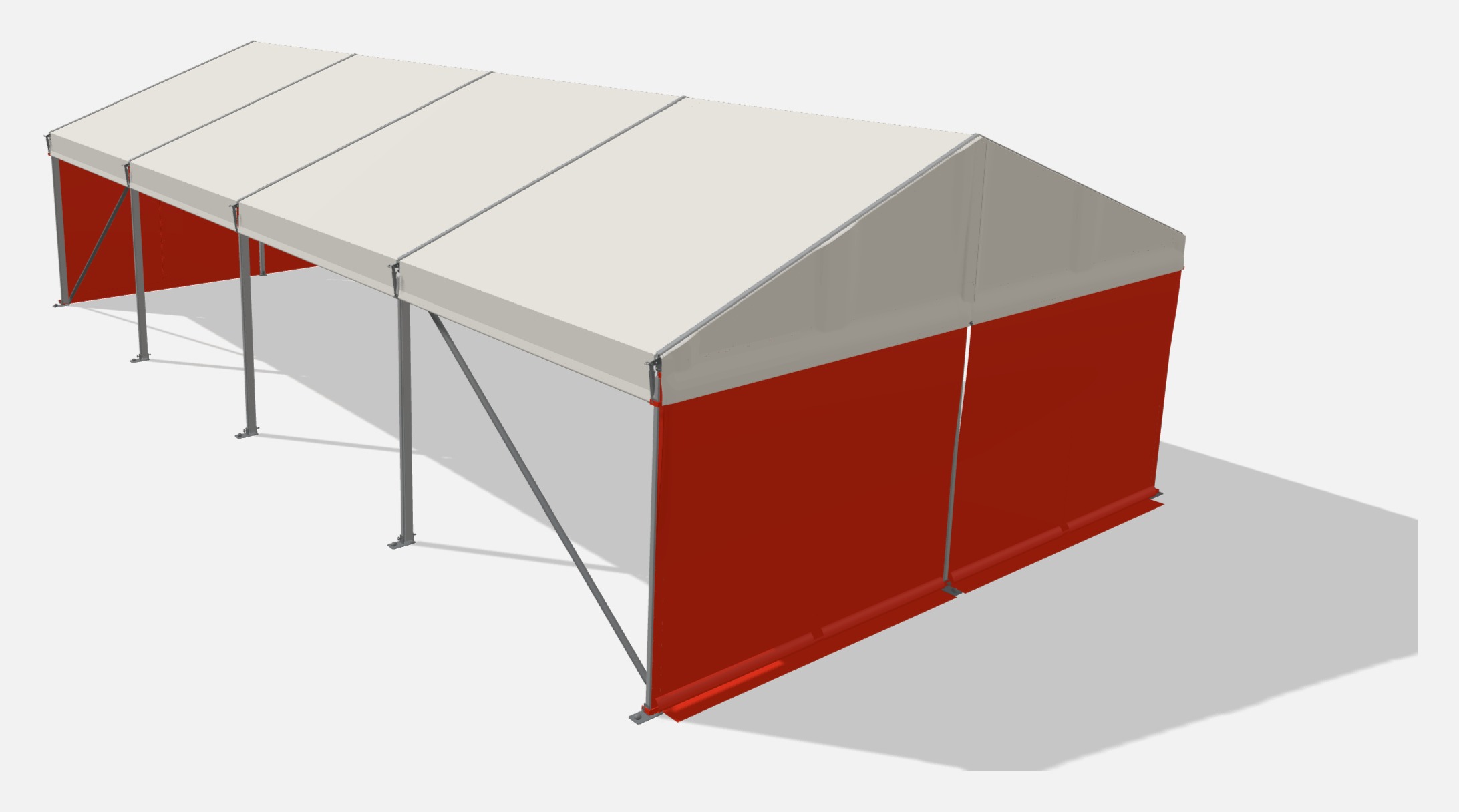
- 1Fit the S00613 Bar Tension 2t Gable Corner Purlin gable corner purlins: plain end onto the eave insert pin of the corner S00007 Side Upright with Eave Insert first, then drop the hook end into the S00382 Gable Upright 2 track (bar tension) bracket loop.
- 2Each gable takes two CP6001 Walls, one each side of the S00382.
- 3Feed the wall’s outer keder into the gable-side track of the corner S00007 Side Upright with Eave Insert from the top of the leg, and slide the wall down.
- 4Feed the six sail slides into the outer track of the S00613 through the milled opening at mid-length, and slide them along to hang the wall.
- 5Lace the wall closed down its centre seam.
- 6Slide an S01304 Gable Wall Bar Bottom through the wall pocket. Pull the outer D00201 Flip Cotter on each foot pin, hook the bar from the centre foot pin to the corner foot pin, and refit the D00201. The bar tensions the wall and holds it in place.
- 7Lay the 150mm sod cloth flat on the ground outside.
Hang the side walls
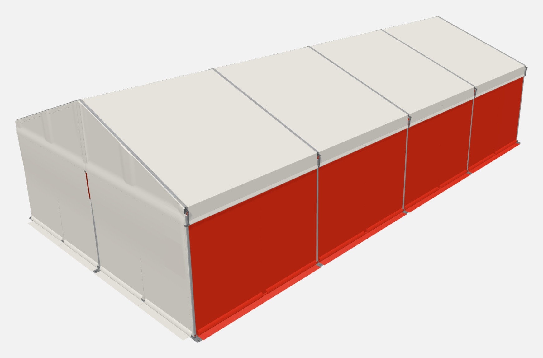
- 1One CP6001 Wall per bay per side. Feed both keder edges into the side tracks of the two uprights from the top of the legs, and slide the wall down.
- 2Feed the six sail slides into the outer track of the S00612 Eave Purlin through the milled opening at mid-length, and slide them along to hang the wall.
- 3Lace the wall closed down its centre seam.
- 4Slide an S01201 Side Wall Bar (bottom) through the wall pocket. Pull the outer D00201 Flip Cotter on each foot pin, hook the bar on, and refit the D00201. The bar tensions the wall and holds it in place.
- 5Lay the sod cloth flat on the ground outside.
Final inspection
- 1Walk round outside: every keder is fully seated, all lacing is tied off, sod cloth lies flat.
- 2Walk round inside: every D00201 Flip Cotter, D11001 4mm R Clip and D11003 3mm R Clip is in place.
- 3All stakes are tight. Re-check after heavy rain or wind, and daily while the tent stands.
Optional: S01701 portal brace
Fit only where an S01701 Party portal brace is to be used. It replaces the S01605 diagonal bar on the left side of bay 1 and is fitted once the frame is fully assembled, just before the covers.
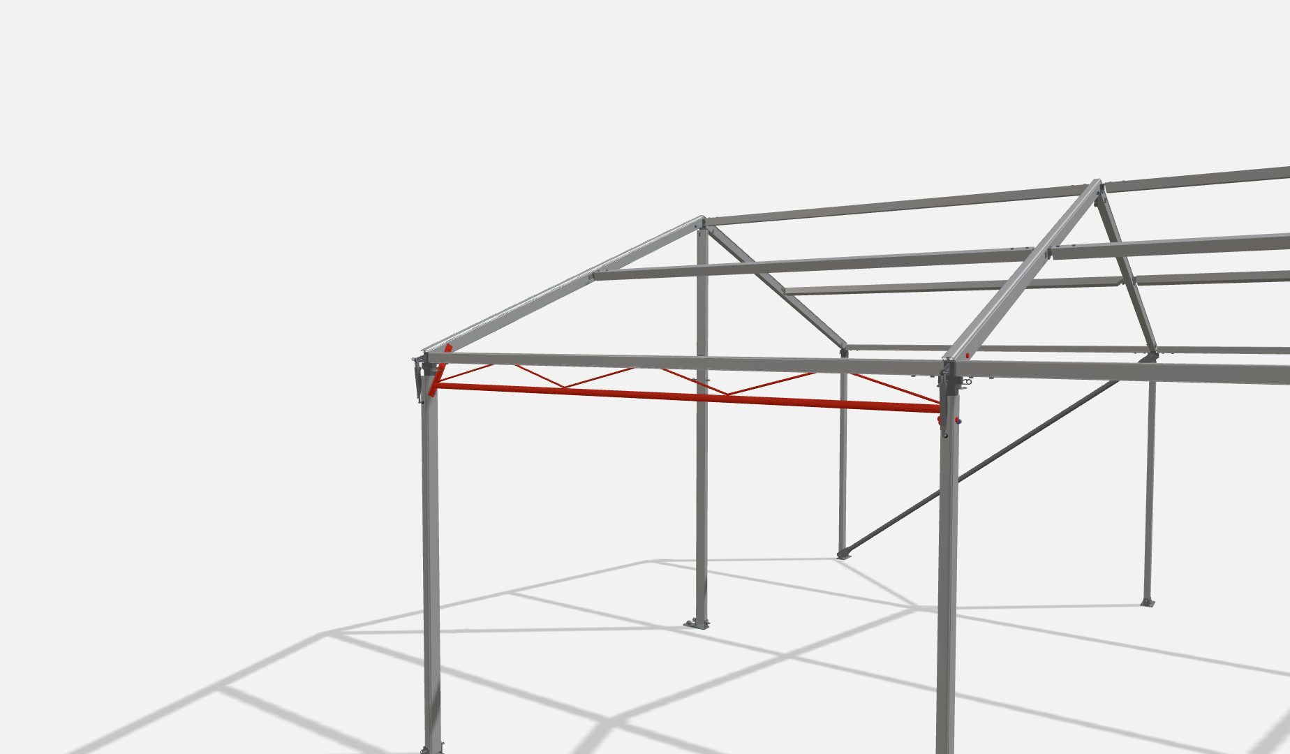
- 1Take out the S01605 diagonal bar from the left side of bay 1 (between spans 1 and 2), with its D00201.
- 2At the left eave of spans 1 and 2, take the N22003 L pin and its D00201 out of the rafter eave hole.
- 3Offer the S01701 up inside bay 1: an end plate against the bay 1 face of each left side upright, the top holes over the rafter eave holes.
- 4At each end, push an M12 x 75 bolt from the far side of the frame through the rafter eave hole and the top end-plate hole, and fit an M12 nylock nut.
- 5Bolt each bottom end-plate hole through the S00007, 275mm below, with an M12 x 75 bolt and M12 nylock nut. Tighten all four bolts.
Pack-down
Pack-down runs in reverse order, working from the front gable to the rear.
- 1Side walls: pull out the S01201 Side Wall Bar (bottom), unlace the centre seam, lift the S01201 top bar off the tensioners and slide the wall up out of the tracks.
- 2Gable walls: the same, with the S01304 Gable Wall Bar Bottom and S00613 Bar Tension 2t Gable Corner Purlin. Fold all walls clean and dry.
- 3Open the N73010 levers, unhook the S01201 roof tension bars and slide them out of the valance pockets. Pull each roof cover out of the tracks eave to eave, then pull out the gable triangles.
- 4If an S01701 portal brace is fitted in bay 1, unbolt it and refit the S01605 Diagonal Bar before lowering span 2, or keep it in until the bay 1 purlins come out.
- 5Remove the last bay braces, and unpin the front gable upright foot from its baseplate.
- 6Starting at the front: hold the front gable span (A-Frame), unhook the last bay purlins, lower it on its foot pins and dismantle it flat, unpinning the gable upright from the ridge. Repeat for each central span (A-Frame), working back.
- 7Unpin the rear gable upright foot from its baseplate. Refit the bay 1 braces in their temporary position (step 04) to hold Span 1 (A-Frame). Unhook the bay 1 purlins and lower Span 2 (A-Frame), then lower Span 1 (A-Frame) and remove the braces.
- 8Pull the stakes with a stake puller, then lift the ground plates. Count every pin, cotter and clip back into its bag.